ECY Series Motor
Wiring Diagrams
Single Speed
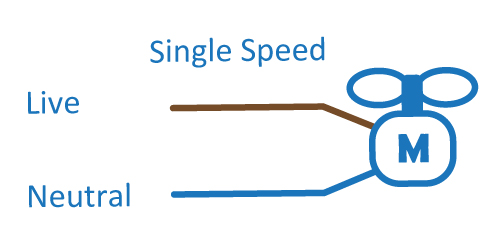
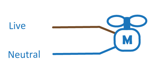
Single speed is the entry-level and is a direct replacement to a shaded pole motor. By connecting the live and neutral wires to VAC input, the motor will energize and run at pre-set speed and direction.
Multi Speed
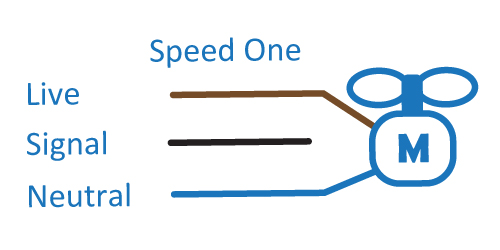
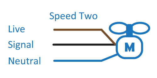
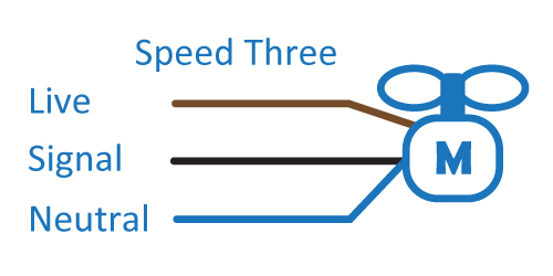
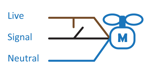
Multi speeds are available by using the signal wire. This allows for “boost” operation when cooling is required quickly, and “trickle” operation once preset temperature has been reached.
Reverse On Start
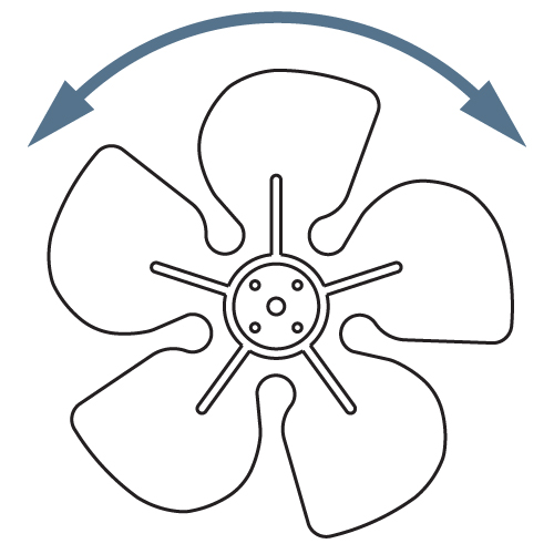
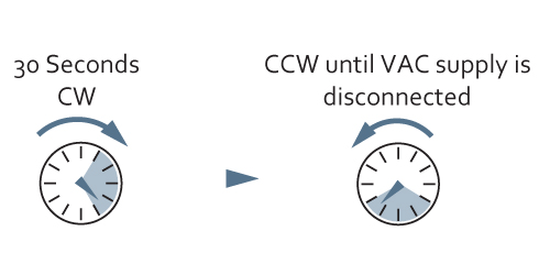
On start-up, the motor will rotate in reverse direction at preset speed and time, thereafter, the motor will then rotate in the correct direction at preset speed until VAC input is disconnected. This function helps to remove any dust that has accumulated in the condenser fins, ensuring maximum cooling efficiency and prolonged life.
Reverse on Demand
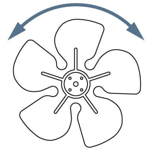
By using the signal wire connected to a relay, it is possible to define the time and duration of reverse operation as required. This function can be used during evaporator defrost cycle to ensure there is no excessive build of ice in the refrigeration system or remove dust from condenser fins, ensuring maximum cooling efficiency and prolonged life.
Relay Function
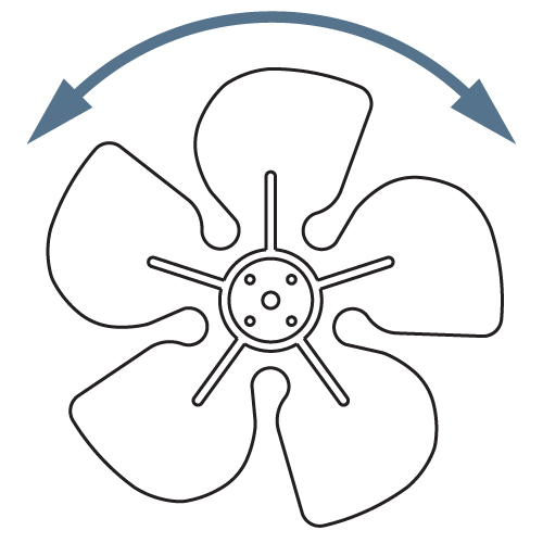
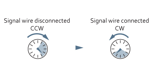
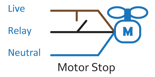
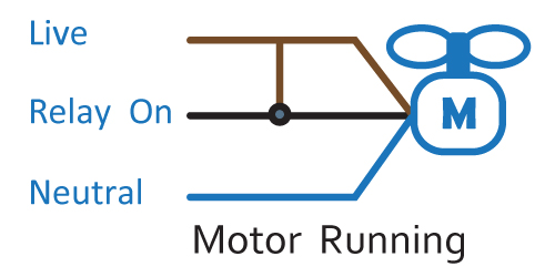
By using the signal wire as a switch, this allows constant VAC supply to the motor. Wiring below illustrates when black is disconnected, the motor will go in reverse direction for preset time and then stop. If signal wire is then connected to live, the motor will rotate in correct direction until signal wire is disconnected, and then the motor will go in reverse direction for preset time and then stop.
Product Compliance
